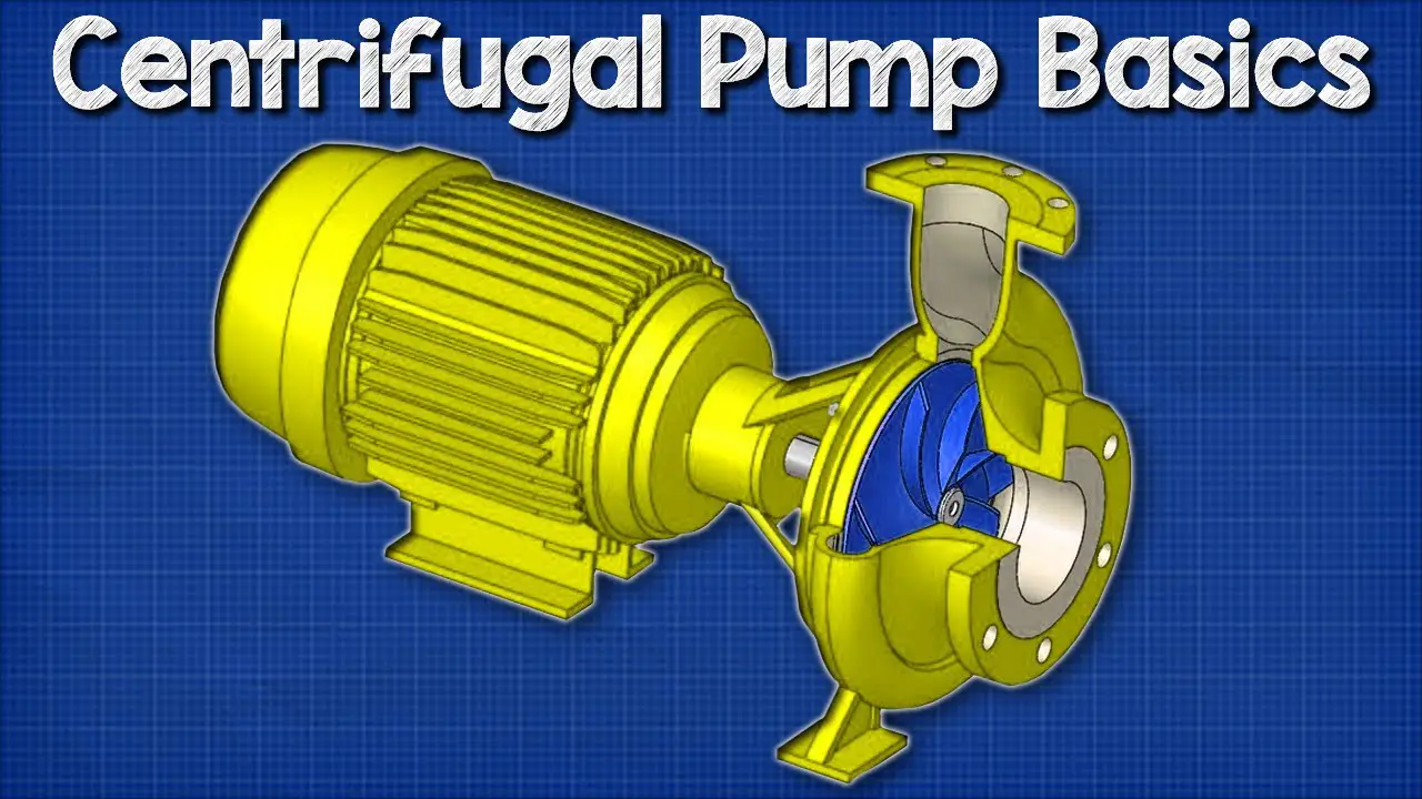
What is Centrifugal Pump?
A centrifugal pump is a hydraulic machine that converts mechanical energy into hydraulic energy by applying centrifugal force to fluid. This apparatus rotates to impart a constant velocity upon a liquid, which is then transformed into a flow. It is the mechanical components that make centrifugal pumps work.
This mechanical assembly includes a pump shaft mounted on bearings, a sealing mechanism to prevent leaking, structural components to handle loads and stresses, and wear surfaces to return the pump to its original specifications.
What are the Components of a Centrifugal Pump?
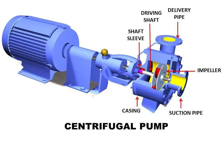
A centrifugal pump’s major components are as follows::
i) Impeller:
When it comes to rotating at high speeds, it has blades or vanes in the form of backward-curved spirals, which are placed inside a spiral casing. It is used as a rotating device, such as an impeller, to increase the flow’s kinetic energy. An internal combustion engine or electric motor prime mover drives the impeller inside the Volute casing, making the impeller spin.
There are Three types of impeller:
a) Open Impeller:
Smaller pumps with open impellers are more convenient to clean and maintain than larger pumps. Unlike other impellers, open impellers have no walls to protect the vanes, making them more vulnerable to damage than other impellers.
b) Semi-Closed Impeller:
Semi-closed impellers can transport fluids with a back wall that adds strength to the impeller, but the other side of the impeller is exposed to the pump housing’s interior. Semi-closed impellers are less efficient than closed impellers.
c) Closed impeller:
This impeller has a stronger front and back wall around its vanes than the semi-closed impeller. Larger pumps with high-speed operation typically employ closed impellers.
ii) Shaft:
When connected, it is the central part of the pump that rotates along with the impeller. The shaft is linked to the prime mover to get power. The shaft is the right size for the ball bearing.
It is an airtight passage that surrounds the impeller in the rotor. Water kinetic energy is converted to pressure energy before it leaves the casing and enters the delivery pipe because it is constructed this way.
iii) Casing:
It serves as a cover to keep the system safe. It is the casing that stabilizes the impeller-generated velocity. Centrifugal pumps have three casings: a) the volute casing, b) the vortex casing, and c) the casing with guide blades.
a) Volute Casing:
The impeller’s discharge fluid is collected and routed to the discharge nozzle by the volute casing, which is designed to guide the flow out of the impeller and convert the kinetic energy into static pressure.
b) Vortex Casing:
When using Vortex Casing, a circular chamber is provided between the casing and the impeller. Compared to Volute casing, this is a much better option for valve housing.
c) Casing with Guide Blades:
A series of guide blades surround the impeller in the casing with guided blades. The diffuser is a ring that holds the guide blades. The guide vanes must be designed so that water exiting the impeller will not be shocked upon entering them.
The surface area of the guide vanes grows to slow the flow of the liquid and raise its pressure. Water flows through the surrounding casing after the guide vanes. Most of the time, the impeller and casing are concentric.
iv) Suction Pipe with Foot Valve and Strainer:
The impeller’s inlet is connected to a suction pipe, and the other end is lowered into the water sump. The foot valve and filter are located at the water’s edge. The foot valve is a one-way valve that opens upwards when pressed down on it. The centrifugal pump is protected from blockage by a filter that removes unwanted particles from the water.
v) Delivery Pipe:
A pipe is attached to the pump’s discharge port at the lower end to get the liquid to the desired elevation. A valve near the pump’s outlet on the delivery pipe controls the flow of the pump’s output into the delivery pipe.
How does a Centrifugal Pump Work?
The primary function of a pump is to move liquids from low-pressure areas to high-pressure areas. The impeller rotates as a result of the induction motor’s rotation of the shaft. When the impeller rotates, a low-pressure area is created, and water from the reservoir is drawn into the pump’s inlet (any fluid naturally moves from a region of high pressure to low pressure). Axially, the water enters the impeller.
Water is pushed outward by the rotating impeller and into the volute section. From the beginning of the volute to the discharge line, the surface area grows steadily. The mass flow rate through any section of a stream tube is constant, according to the principle of mass conservation.
As a result, the relationship between speed and area is inversely proportional. Because of this, the flow’s kinetic energy decreases as the area increases. According to Bernoulli’s equation, the decrease in kinetic energy leads to increased pressure energy. The liquid will rise to the desired level due to the increased pressure.
What are the Types of Centrifugal Pumps?
Centrifugal pumps are used in various industries worldwide, with many different types. These pumps are subdivided depending on the number of impellers, type of casing, orientation, and stages.
1. According to the number of impellers
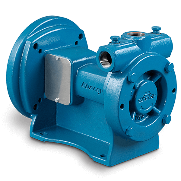
i) Single Stage Centrifugal Pump:
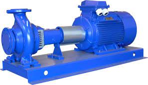
Courtesy: pump-hv.com
This pump has only one impeller, which rotates on a shaft within the pump casing when an electric motor powers it. Numerous design variants have been developed for this basic pump to meet a wide range of duty requirements.
ii) Multistage Centrifugal Pump:
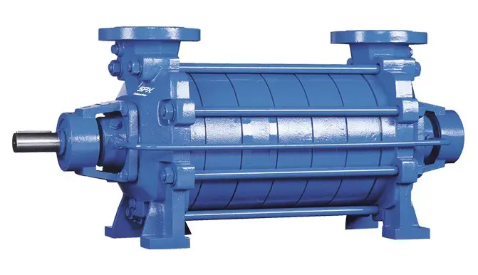
Courtesy: spxflow.com
In a multistage pump, the fluid passes through multiple connected impellers to form the flow. In a single-stage centrifugal pump, both the type of impeller and the circumferential speed influence the pump’s output.
2. According to Type of Casing:
i) Turbine Pump:
Courtesy: psgdover.com
This pump is one of the most well-known centrifugal pumps on the market. There are a variety of blades that can be attached to the impeller of this pump. Stability is provided by the diffuser ring on which these blades rest. The distance between the blades determines which way the liquid flows. A great deal of pressure is exerted on the fluid as it exits the impeller cavity.
Liquid flows from the blades into a volute, concentric or circular housing. These pumps have the advantage of being able to convert 75% of the fluid kinetic energy into pressure. However, the price of these pumps is prohibitive.
ii) Volute Pump:
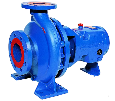
Courtesy: lentech.com
In these pumps, the impellers are protected by a volute casing. It is possible to design this casing so fluids of equal velocity can exit and enter the pump. The amount of energy that is lost as a result of this design is negligible. These pumps’ lack of potential energy conversion means that kinetic energy is wasted.
3. According to Orientation of Fluid:
i) Radial Flow Pump:
Courtesy: starpumpalliance.com
Fluid exits the impeller of radial centrifugal pumps after the impeller has rotated 90 degrees with the suction. It is a common classification for centrifugal pumps. Incoming and outgoing fluid flows through horizontal and vertical flanges, respectively.
Perpendicular to the pump’s shaft, the discharge will be. This design is frequently employed when the flow is restricted, and the discharge pressure needs to be raised. Therefore, a radial design is a high-pressure pump with a low flow rate. It is the most common type of pump found in the oil and gas industry.
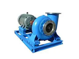
ii) Axial Flow Pump:
Courtesy: inspection-for-industry.com
In an axial flow pump, the suction is parallel to the impeller’s direction of travel. When using an axial flow pump, there is no change in the flow direction. The fluid flows into and out of this pump perpendicular to the impeller. The pipe contains an impeller. The impeller of this pump is equipped with three or four blades.
As a result of the pump blade’s design, the water has discharged either parallel to the impeller or perpendicular to it. Impeller blades are aligned parallel, resulting in low water pressure when pumping. These pumps are best suited for high-volume, low-pressure pumping.
iii) Mixed Flow Pump:
Courtesy: ingeniovirtual.com
The interval between radial and axial denotes an intermediate direction between the two (along the axis). At first, water moves in a straight line along the impeller axis, but after a short distance, it begins to move vertically to the impeller axis.
4. According to Position of Centrifugal Pump:
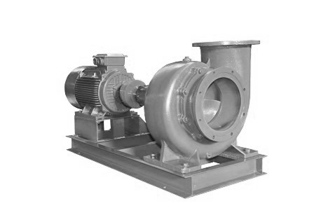
i) Horizontal Centrifugal Pump:
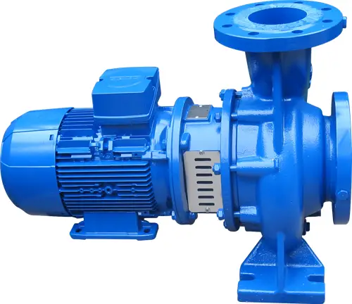
Courtesy: northridgepumps.com
The shaft of a horizontal centrifugal pump runs horizontally. These pumps easily adapt to various add-on components, such as electric motors or turbines. Compared to a vertical centrifugal pump, the horizontal centrifugal pump operates at lower pressures and temperatures than a vertical centrifugal pump.
These pumps are designed to deliver fluid at a high rate of speed. As a result, they are extremely productive because of their high-quality construction. Horizontal centrifugal pumps are known for their quiet operation, simple installation, and low maintenance. As a result of their size, they have a significant disadvantage.
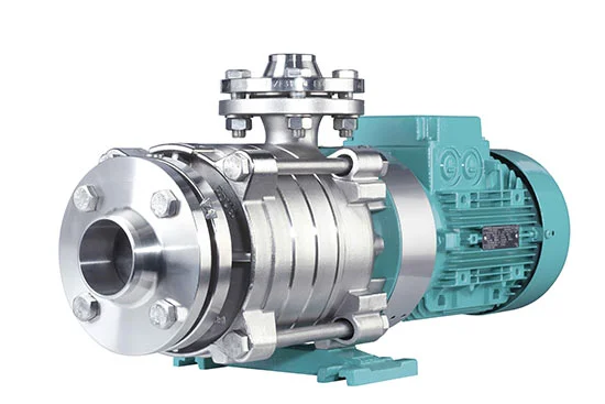
ii) Vertical Centrifugal Pump:
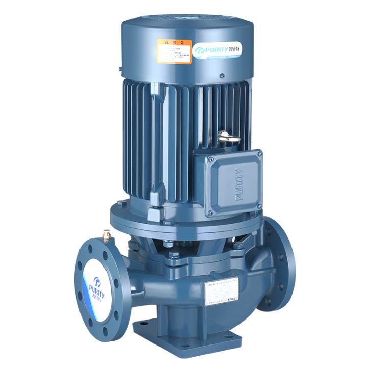
Courtesy: purityfire.com
The shaft of a vertical centrifugal pump travels vertically. Negative displacement pumps such as these are preferred for transferring chemical substances quickly. Compared to horizontal centrifugal pumps, their thickness and operating temperature are higher.
High-temperature and high-pressure fluids are the primary applications for these pumps. Their fluid flow rate is smooth, and they don’t require priming; however, they make a lot of noise and don’t have much power.
iii) Submersible Centrifugal Pump:
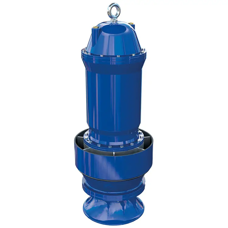
Courtesy: ruhrpumpen.com
These pumps are used in municipal, rainwater, residential, industrial, and commercial applications and provide underground soil, rainwater, sewage, and chemicals. They are designed for low flow and high head fluids and high flow and low head fluid rates. Because they are already submerged in water, these pumps do not require manual priming. They also eliminate the cavitations issue. These pumps frequently exhibit leakage issues, which can cause damage to the pump assembly’s internal components.
What are the Pros of Centrifugal Pumps?
- There is no leakage in the pump because there is no drive seal.
- It is capable of pumping hazardous liquids.
- There is virtually no sound.
- There are hardly any losses due to friction in this process.
- The efficiency of the pump is almost at 100 percent.
- The gap prevents no heat transfer between the pump chamber and the motor.
- Compared to other pumps, centrifugal pumps have the smallest amount of wear.
- A gap between the pump chamber and the motor prevents water from entering the motor.
- Centrifugal pumps use magnetic couplings that disintegrate at high loads to avoid damaging the motor.
What are the Cons of Centrifugal Pumps?
- Cavitations can occur if the selected pump’s net positive suction head is too low.
- The fluid properties of the pump may lead to corrosion inside the pump.
- Due to low flow, the pump may overheat.
- Suspended solids can cause impellers to wear out too quickly, a problem that can be exacerbated.
- Pumps that use a centrifugal magnetic drive can have issues with liquids that contain ferrous particles. The pump may eventually cease functioning as particles accumulate on the impeller magnet. The coupling loses some of the energy. It’s because of a small amount of magnetism. If heavy loads are applied suddenly, the coupling may slip.
- Centrifugal pumps cannot function unless primed with the fluid they are designed to pump. A pump impeller becomes gas-bound if the pump casing is filled with gases or vapors. It may cause the pump to stop working entirely.
- Since centrifugal pumps do not use suction to move water, their suction power is minimal.
- When the centrifugal pump is in use, it may use too much power.
What are the Applications of Centrifugal Pumps?
- In agriculture, centrifugal pumps are used extensively. Farm machinery, such as tractors and combine harvesters, are powered by water from reservoirs and lakes. Pesticides and fertilizer can also be sprayed on crops using centrifugal pumps.
- It is common practice in chemical plants to use centrifugal pumps to move fluids around. Typically, the fluid is transferred from one tank or process to another.
- Centrifugal pumps are common in water treatment facilities because of their versatility. When water is needed to be moved from one place to another, a water pump is typically used.
- Centrifugal pumps transport crude oil from the wellhead to storage tanks or pipelines. Aside from moving liquids between units and injecting chemicals into wells, offshore oil and gas production platforms use centrifugal pumps.
- Centrifugal pumps are commonly used in paper mills, one of the most common industrial applications. Centrifugal pumps are used to move the paper stock during the pulping process.
- Centrifugal pumps are ideal for power plants because they can handle large volumes of fluid and operate at high pressures. All of the water in the cooling system, fuel oil, and lubricant is transported by centrifugal pumps in the cooling system.
- Various centrifugal pump applications can be found in food processing facilities. Centrifugal pumps are commonly used in food processing plants for various purposes.
- Because centrifugal pumps can move large volumes of fluids at high pressures, they are commonly used in military applications. Additionally, they are frequently found in aircraft fuel systems, shipboard hydraulic systems, and equipment used on the ground.
- Firefighting, water supply, and fuel transfer are just some of the uses for centrifugal pumps. It is also possible to move sewage and other waste materials using centrifugal pumps.
Conclusion:
A centrifugal pump moves rotational energy from one or more impellers. Flow velocity and pressure are increased and directed towards the pump outlet by the impeller’s motion. With their straightforward construction, centrifugal pumps are simple to use and maintain.
Centrifugal pump designs offer simple and low-cost solutions for low-pressure, high-capacity pumping applications involving low viscosity fluids such as water, solvents, chemicals, and light oils. Most commonly, water supply and circulation, irrigation, and chemical transfer are used in petrochemical plants.
FAQ:
What are the main features of a centrifugal pump?
Centrifugal pumps accelerate fluid to the outer rim of an impeller, where it is converted to kinetic energy. The amount of energy given to the liquid is directly proportional to the speed of the impeller’s vane tip.
What is a common problem in centrifugal pumps?
Centrifugal pumps often have impellers that rotate in the wrong direction. The pump could be severely damaged if the impellers turn the wrong way.
What is priming in a centrifugal pump?
Priming can be defined as the process of getting something ready for use by putting it through its paces. It would be best if you filled a centrifugal pump with water for it to function properly. Centrifugal pumps look like this when they’re working properly. Upon removal of the air, the pump will restart.
Which motor is used in the centrifugal pump?
A DC shunt motor can drive a constant-speed line shaft, a lathe, a centrifugal pump, a small printing press, and a paper mill.
Which factors affect the performance of a centrifugal pump?
It is important to consider the number of solids in the fluid and their size, shape, and abrasive properties. Any operation’s pumping conditions, such as temperature and pressure, must be considered. Examples of this might include high-temperature pumping requiring unique gaskets, sealing, and mounting designs for the equipment involved.