Introduction: What is a gas turbine, and how does it work? A gas turbine is a combustion engine that converts natural gas or other liquid fuels to mechanical energy in the core of a power plant. This energy then powers a generator, which generates the electrical energy distributed to homes and businesses via power lines.
Gas Turbine Cycle
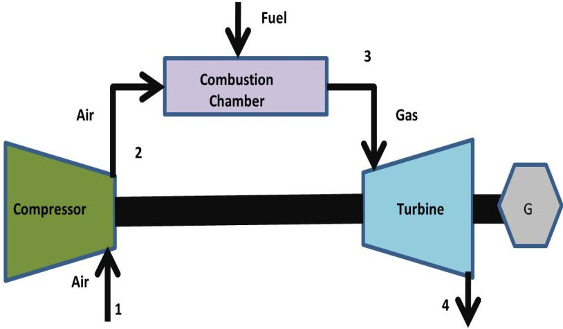
The turbine cycle will describe a gas turbine and how it works. The basic idea behind the gas turbine engine can be applied to any engine that gets power from a chemical fluid.
The basic four pillars for any internal combustion engine are:
1. Intake of air (and possibly fuel).
2. Air Compression process
3. Combustion of fuel, Burning process
4. Expansion, where the converted power is placed on utilizing.
In the example of a piston engine, Including the engine in a car or requite airplane engine, the input, compression, combustion, and expansion steps take place in the same place at different times as the piston moves up and down.
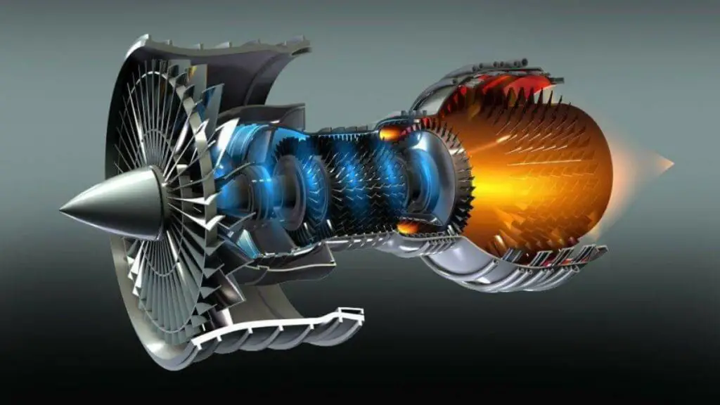
In the turbine engine, these same four steps happen simultaneously but in different locations. As a result of this basic difference, the turbine has an engine segment called:
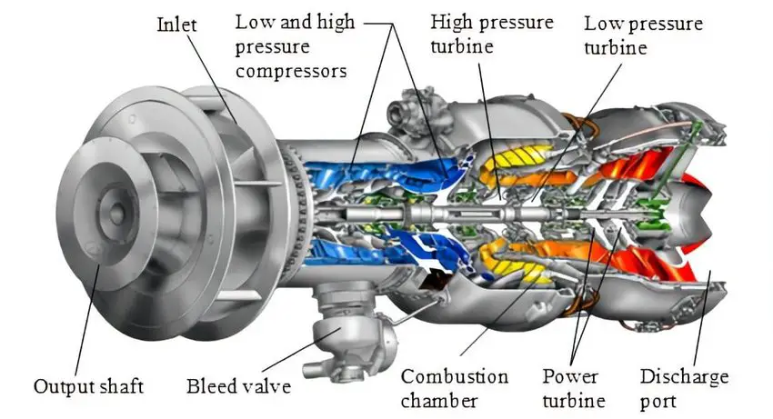
1. The inlet segment
2. The compressor segment
3. The combustion segment
4. The turbine (and exhaust) segment.
The turbine segment of the gas turbine engine produces usable output shaft energy to drive the propeller. However, in inclusion, it must also provide energy to operate the compressor and all engine parts. It does this by dilating the high temperature, pressure, and velocity gas and converting the air energy to mechanical energy in the shape of shaft energy.
Therefore, a large mass of gas must be supplied to the turbine to produce the necessary energy. The compressor supplies this gas mass, which draws the gas into the engine and compresses it to supply high-pressure air to the turbine.
The compressor converts mechanical power from the turbine to gaseous power through pressure and temperature. If the compressor and the turbine were hundred percent well organized, the compressor would supply all the air required by the turbine. Likewise, the turbine would supply the required energy to drive the compressor. In this case, a permanent motion machine would survive. However, frictional losses and mechanical system inadequacy do not allow a permanent motion machine to work.
Additional energy should be added to the air to put up these losses. Energy output is also desired from the engine. Thus, energy should be added to the air to produce this excess energy. Energy adding to the system is expert in the combustor.
Chemical energy from the fluid as it is burned is turned to gaseous energy in the shape of high temperatures and high-rise velocity as the gas goes by the combustor. Finally, the gaseous energy is changed back to mechanical energy in the turbine, granting energy to drive the compressor and the output shaft.
Working Principle of Gas Turbine
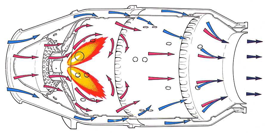
Through the gas turbine working principle, it is easy to understand what is gas turbine and how it works. Fresh air enters the compressor at an ambient temperature where it’s compressed. As the air is squeezed, it gets hotter, so pressure and temperature increase. This is the compression stage.
Now let’s talk about combustion and how it happens.
The high-pressure gas is injected into the combustion chamber, where the fuel is burned at normal pressure. to produce a high-pressure and high-velocity gas
And how is power produced from this mixture? Now let’s talk about the last stage: the exhaust.
The high-temperature gas created from the ignited mixture moves the turbine blades, forcing them to spin at more than 3000 RPMs. This is how chemical energy is converted into mechanical energy.
This spinning causes the driveshaft connected to the generator to rotate, generating electricity.
Features:
- Gas-turbine is used in aircraft propulsion and electric power generation.
- The Thermal efficiencies are up to 44 %.
- Suitable for combined cycles
- High power to weight ratio, too high reliability, long life
- Fast start-up time, about two min, compared to our hours for steam-propulsion systems.
- High back work ratio (ratio of compressor work to the turbine work), up to 50%, compared to a few per cent in steam power plants.
Brayton Cycle ( The engineering behind Gas turbines)
The Brayton cycle is perfect for gas-turbine engines in which the working fluid undergoes a closed process. The combustion and exhaust procedures are designed by constant-pressure heat addition and rejection.
Let’s get a little bit into engineering and scientific terms :
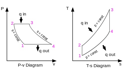
The Brayton ideal cycle is designed up of four internally reversible procedures:
- 1-2 isentropic compression (in the compressor)
- 2-3 const. pressure heat-addition (in the combustion chamber)
- 3-4 isentropic expansion (in the turbine)
- 4-1 const. pressure heat rejection (exhaust)
ENGINE SECTIONS
The air inlet is designed to deliver the supply air to the compressor with minimal loss of power resulting from thrust or pressure loss of the piston; this means that the airflow to the compressor must be free of turbulence to achieve maximum operating efficiency. Proper intake design contributes significantly to aircraft performance by increasing the ratio of compressor discharge pressure to intake manifold pressure.
This fraction is the outlet pressure divided by the inlet pressure. The amount of gas passing through the engine depends on three factors:
- Compressor speed
- The forward speed of the aircraft
- The density of the surrounding (surrounding) air
The type of gas turbine engine determines the type of turbine intake. The inlet valve for this type of motor is bolted to the front of the motor. These engines are mounted on the wings, aft of the fuselage, and several are in the vertical branch.
Because on most modern turbos, the large fan is the first part of the aircraft that comes into contact with air, anti-icing should be provided. This will prevent chunks of ice from forming on the front corner of the inlet and damaging the fan. Warm air is drawn from the engine’s compressor and is routed through the intake to prevent ice formation. If the inlet guide vanes are designed to be used to straighten the airflow, then.
Anti-icing gas also flows through them. The intake also has some noise-reducing materials that absorb fan noise and keep the engine running quietly. Turboprops and turboshafts may use an inlet screen to help filter out ice or debris that has entered the machine. A deflector blade and a heated intake blade prevent frost or large pieces from entering the engine.
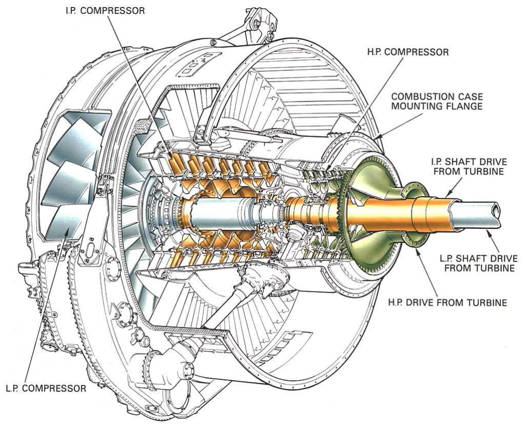
Compressor
The compressor part of a gas turbine engine has too many functions. Its primary function is to supply gas in sufficient quantity to meet the requirements of the combustion burners. For the compressor to fulfil its purpose, it must increase the pressure of the mass of air received from the air intake pipe and then discharge it into the burners in the required quantity and pressure.
The secondary use of the compressor is to supply waste gases for many purposes in the engine and aircraft. The extracted air is drawn from any of the different pressure stages of the compressor. The exact location of the vents is, of course, dependent on the pressure or temperature required for the particular job.
Ports are small openings in the compressor housing near the particular stage from which air is to be discharged; thus, different degrees of pressure are available simply by double-clicking on the appropriate degree.
Air is often removed from the final or highest pressure stage, where the air pressure and temperature are at their maximum. Sometimes this high-pressure air may need to be cooled. If used to pressurize the cabin or for other purposes for which excessive heat would be uncomfortable or harmful, the air is sent through the air conditioning unit before entering the place.
Bleed air is used in many different ways. Some of the current applications of air sampling are:
- Cabin pressurization, heating, and cooling;
- De-icing and anti-icing equipment;
- Pneumatic starting of motors; and
- Auxiliary Propulsion Units (ADUs).
Types of Compressors used in gas Turbine
The two main compressors currently used in gas turbine aircraft engines are.
1-Centrifugal flow
2-Axial flow
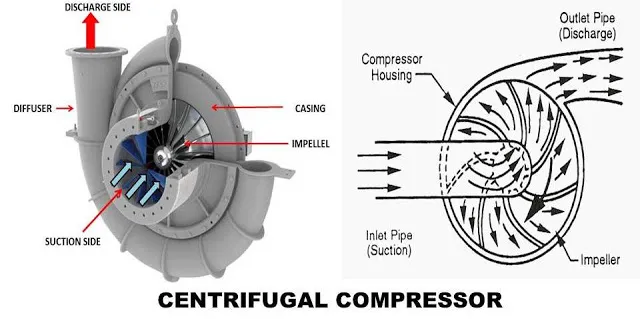
Centrifugal‐Flow Compressors
A centrifugal compressor consists of an impeller (rotor), a diffuser (stator), and a compressor tube. Centrifugal compressors have a very high-pressure rise per stage that can be 8:1. Centrifugal compressors are usually limited to two steps for efficiency reasons. The two main functional parts are the impeller and the diffuser. Although the diffuser is a separate part and is placed inside and bolted on, the manifold of the entire assembly (diffuser and manifold) is often referred to as a diffuser.
Centrifugal Compressor Parts
The centrifugal air compressor has five main parts, which are listed below:
- Impeller
- Casing
- Diffuser
- Inlet and Outlet valves/ports
- Collector
Impeller
Higher tensile strength and flow The rotor or impeller is one of the essential components of a centrifugal compressor.
The impeller or rotor of a centrifugal air compressor is a disk with a vane assembly attached to the compressor shaft. A varying number of curved vanes connect to this disc.
These vanes provide a diffusion channel for the working gas or air. These curved blades vary from 15 to 20 in a single impeller of a centrifugal compressor.
The compressor impeller imparts speed or velocity to the air or gas through vanes attached to the rotating disc. Depending on the required performance, these blades can be tilted backwards, radially or forwards. Most multi-stage compressors use backwards inclined vanes for maximum efficiency. Strength than austenitic and ferritic types
Casing
A casing primarily protects the above centrifugal compressor components. A container is a tight passage for air (or any other fluid) around the impeller.
The casing is designed so that the kinetic energy of the air is released at the discharge port of the impeller, but this kinetic energy is converted to pressure before the air leaves the casing. The housing consists of several bearings that support the rotor axially and radially. It is made of steel or cast iron.
The case has two main types:
- Splits Vertically
- Splits Horizontally
Diffuser
The impeller sends air into the diffuser channel at a very high speed. This diffuser usually affects the two walls that form the radial channel. These arrangements slow the air or gas and convert dynamic pressure to static pressure.
A diffuser channel is a small space between adjacent diaphragms that generally turn the airflow 180 degrees to guide it to the next chute. It is part of the centrifugal compressor before the outlet section. After the diffusion part, the air or gas goes into the collector.
Inlet and outlet valves
The inlet port of the compressor is used to draw in air or gas inside the compressor. In contrast, it uses the outlet port to release compressed air or gas.
Collector
Behind the last impeller, the air or gas is collected and directed to the outlet section. It uses a component to accumulate air or gas emitted by a diffuser known as a collector, scroll, or volute.
The manifold may also have valves and other devices to control the compressor. The collector is the last part of the centrifugal compressor. Finally, the discharge pipe is connected to the manifold, where the compressed air or any other fluid flows out and transfers to the desired location or section.
How do Centrifugal‐Flow Compressors work?
The centrifugal compressor working principle differs slightly from a rotary or reciprocating compressor.
The operating principle of a centrifugal compressor is slightly different from a rotary or reciprocating compressor.
A centrifugal compressor works as follows:
During start-up, air is supplied to the centrifugal compressor from an air reservoir or other source.
After entering the compressor, it hits the impeller.
1-This impeller has multiple radial blades that rotate with the rotation of the impeller.
2- When the air hits the radial blades of the impeller, the air is pushed by centrifugal force into the centre of the impeller.
3- After impact, the impeller blades provide the kinetic energy of the air; due to this, its velocity (velocity) increases.
4- The air enters the diffuser area after passing through the impeller. This diffuser has stationery supplies. After entering the diffuser space, the speed or velocity of the airflow starts to decrease.
5- According to Bernoulli’s principle, the square of the velocity is inversely proportional to the pressure. Before the air is pulled into the centre of the impeller, the spiral body or diffuser changes the speed of the air into pressure energy. Under most conditions, the impeller pressure increase is approximately equal to the diffuser pressure increase.
The diffuser is a static (stationary) part of the compressor that accompanies the airflow as it exits the rotor. This deceleration eventually leads to a further increase in pressure. The diffuser and rotor or impeller account for approximately 35% and 65% of the total force generated by the compressor, respectively. The centrifugal compressor strongly influences the air compression process.
Axial‐Flow Compressor
An axial compressor has two main elements: a rotor and a stator. The rotor has blades fixed to the spindle. These blades drive the air backwards similarly to a propeller because of their angle and airfoil profile. The rotor, which rotates at high speed, sucks in philosophy at the compressor inlet and drives it through a series of stages. Air flows along an axial path from inlet to outlet and is compressed at a ratio of roughly 1.25:1 per stage.
Parts of Axial Flow Compressor
The main parts of an axial flow air compressor are listed below:
- Inlet Casing
- Rotor or Blade
- Collector
- Stator Blade
Inlet Casing
The shroud acts as a protector to protect the internal components of the turbine from any damage. A sleeve fixes the stator blades. It’s made of steel or cast iron.
Rotor or Blade
The impeller blades are movable. They are constantly rotating. The vane adds kinetic energy to the gas and increases its gas velocity.
Stator Blade
The blades are static and solid. These vanes convert gas velocity into pressure energy.
Collector
A collector or outlet is an area from where final pressurized gas collects. So, the collector includes the most crucial axial compressor components.
How Axial-Flow Compressor Works
First, the gas is fed to the axial compressor through the inlet. Then, the working fluid flows in a direction parallel to the rotor’s axis.
As a gas or other working fluid moves through the blades of a rotor or impeller, the blades give the gas or different working liquid kinetic energy. This kinetic energy makes the gas move faster.
Following the rotor blades is a row of stator blades on the compressor shaft. After passing through the rotor blade, the gas passes through the stator blade fixed to the compressor housing.
As the gas moves through the stator vanes, its kinetic energy is changed into static pressure energy. Then this final outlet gas is collected through the outlet section of the compressor. Finally, this final outlet gas exits the compressor axially.
Put in an axial air compressor, and the rotor blades increase the velocity of the gas and the diffuser stator blades convert this increase in speed into pressure energy.
Standard functionality is put under more pressure by how the diffusion channel is made. This causes the pressure in each stage of the rotor and stator to rise more quickly. This is the principle of the turbine reaction. For example, if a pressure increase of 50% is achieved in the rotor section, the reaction force is said to be 50%.
Combustion Section
The combustion process occurs in the combustion part, which increases the temperature of the air passing through the engine. This process releases the energy contained in the air/fuel mixture. The central part of this energy is needed in the turbine or turbine stages to drive the compressor. About 2/3 of the power is used to drive the compressor of the gas generator. The remaining control passes through the remaining turbine stages, which absorb more energy to drive the fan, output shaft, or propeller.
Only a pure jet engine allows the air to create all the thrust or propulsion by leaving the rear of the engine in the form of a high-speed jet. These other engine types have some flow at the end of the machine, but most of the thrust or power is generated by additional turbine phases driving a large fan, propeller, or helicopter rotor blades.
Function Of Combustion Chamber
The primary function of the combustion part is, of course, the combustion of the fuel/air mixture and, thus, the supply of thermal energy to the air. To be effective, the combustion chamber must:
- Provide means for proper mixing of fuel and air to ensure good combustion,
- Burn this mixture efficiently,
- Cool the hot products of combustion to a temperature that the inlet guide vanes/turbine blades can withstand under operating conditions, and
- Bring the hot gases into the turbine part.
All combustion chambers contain the same essential elements:
- Cover
- Perforated inner liner
- Fuel injection system
- Some means of initial ignition
- Fuel drain system for draining unburned fuel after engine shutdown
Currently, there are three basic types of combustion chambers, while the individual variants are only in detail. These are the following types:
- Can Type Combustor
- can-annular type
- Ring-type
The can-type combustor is typical of the type used in turboshafts and APUs. Each can-type combustion chamber contains an outer shell or casing, perforated stainless steel (high heat resistant) combustion chamber liner or inner liner.
Turbine Section
The turbine converts some of the exhaust gas’s kinetic (velocity) energy into mechanical energy to operate the gas generator compressor and accessories. The sole purpose of a gas generator turbine is to absorb approximately 60% to 70% of the overall pressure energy from exhaust gases. The amount of energy absorption on a turbine is determined by the load the turbine is driving.
You can use these turbine stages to power a low-pressure compressor, a propeller, and a shaft. The turbine part of a gas turbine engine is located after or behind the combustion chamber. In particular, it is right behind the opening of the combustion chamber.
The turbine assembly consists of two essential elements: the turbine inlet guide vanes and the turbine blades. Various names know the stator element, the three most commonly used being turbine inlet vanes, turbine inlet guide vanes, and nozzle diaphragm.
The turbine inlet nozzle blades are directly behind the combustion chambers and immediately in front of the turbine wheel. This is the highest temperature that comes into contact with the metal parts in the engine. Therefore, the turbine inlet temperature must be controlled, or the turbine inlet blades will be damaged.
After the combustion chamber adds heat to the airflow and sends it evenly to the turbine inlet nozzles, the nozzles must prepare the airflow to move the turbine rotor. The stationary blades of the turbine inlet nozzles are shaped and angled to make a series of small nozzles that release gas at a very high speed. This way, the nozzle converts some of the thermal and pressure energy into velocity energy, which can then be turned into mechanical energy by the turbine blades.
The second purpose of the turbine inlet nozzle is to deflect the gases to a certain angle in the direction of rotation of the turbine wheel. Since the gas stream from the nozzle must enter the passage of the turbine blade while it is still rotating, it is necessary to direct the gas in the general direction of rotation of the turbine.
Diffuser
The diffuser is the divergent part of the engine after the compressor and before the combustion part. It has the vital function of reducing the high-speed discharge air from the compressor to an elevated pressure at a lower speed.
This prepares the air to enter the flame-burning area of the combustion section at a lower velocity so that the combustion flame can burn continuously. The air passing through the flame area at high speed can extinguish the flame.
FAQS
What are the two types of gas turbines?
Two basic turboprop engines are used: fixed turbine and free turbine. The fixed turbine has a mechanical connection from the gas generator (gas-turbine engine) to the reduction gearbox and propeller.
Which cycle is used in gas turbines?
The Brayton cycle, called a Joule cycle, is the basis for almost all gas turbines. In this cycle, fuel and air are compressed, burned, sent through a gas turbine, and released out of the system. Most of the time, exhaust gases heat up fuel or air.
Why is the Brayton cycle used in gas turbines?
The Brayton cycle is an example of a thermodynamic cycle that explains how gas turbines work. The idea behind the Brayton cycle is to extract energy from flowing air and fuel to create usable work that can be used to power many vehicles by giving them thrust.
What gas is used in a gas turbine?
Natural gas is the most preferred conventional fuel for the propulsion of gas turbines. Because of this, it is often used as a reference fuel for comparison of the performance of gas turbine engines.